


RF Listener
 I printed the frame from PLA and that went smoothly. I find that when you design a part specifically for 3D printing you almost always get good results.
I tried some of those decorative first layer patterns for the covers and they came out quite nice. An additional benefit I discovered is that they seemed to have fewer warping issues than the regular linear fill, I think this is because the lines don't all pull in the same direction as the material shrinks.
 For the electronics, I started by designing the circuit in Falstad Circuit Simulator. I tested out the chopper and tweaked the resistor values until it worked well. As I designed the op-amp part of the circuit, I realized it would not be practical to have 0V = 0 Signal, since the op amps don't function correctly near the rails. Instead I made "zero" 224mV.
Once I had the circuit working in the sim, I built it breadboard and used a function generator as input. After fixing a couple of minor issues, the two actually agreed pretty well!
 Next I duct-taped the breadboard onto the frame and tested it out. This turned out to be really convenient for testing improvements.
Using this setup...
I added a peak detector to the amplitude path, which made the quick blips of digital signals much louder.
I added an exponential amplifier before the speaker, to cancel out the log response of AD8318.
Lastly, I moved the gain adjustment to the input side of the circuit instead of the output. This keeps the intermediate amplifiers in a more predictable operating range and also allows the gain adjustment to effect the bar graph as well the audio.
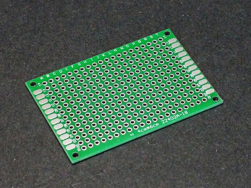 I was planning to assemble the circuit on one of these protoboards.
Honestly that would have been a more time efficient way to do it, but I much prefer designing PCBs to soldering rats-nest protoboard circuits, so I made a PCB instead.
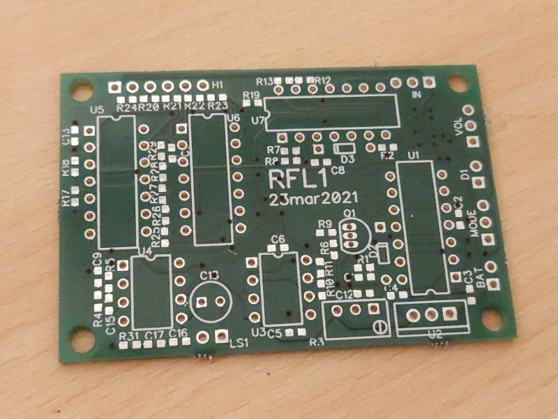 I laid the circuit out in Diptrace, and ordered it from Aisler. 23USD and a few weeks waiting for the deathly slow USPS later, I had PCBs in hand.
I assembled the board manually with tweezers and a soldering iron. If you have a stereo microscope soldering 0603 parts by hand is pretty easy. I didn't take any pictures of that process unfortunately.
The assembled board didn't work right away. Unfortunate, but I guess that's what I get for skipping my pre-order checklist. It turned out that a few of the wires in my schematic were on top of each other but not actually connected. Doh.